

How to Choose the Right Ceramic Knife Gate Valve?

Selecting a Ceramic Knif Gate Valve starts with the material moving through the line, not the catalogue photograph. Particle size, solids concentration, pressure, temperature, and cycling frequency all shape performance. A valve handling fine mineral slurry may face different wear patterns from one cutting through fibrous waste. Small details matter.

The U.S. Geological Survey’s Mineral Commodity Summaries 2025 estimates global bauxite mine production at about 420 million metric tons in 2024. That scale reflects the demanding, abrasive conditions found across mineral processing operations. It does not prove that ceramic is right for every service. Slurry chemistry, impact from coarse particles, and operating cycles still need careful review. No valve is magic.

A practical selection compares the ceramic grade, gate and body construction, sealing arrangement, actuator capacity, and maintenance access. Ask suppliers for service-specific test data, including pressure and leakage results, rather than relying on hardness claims alone. ISO 5208 provides pressure-testing requirements for industrial valves, but application testing may still be needed. One awkward truth: specifications can look complete and still miss real process fluctuations. Confirm the actual operating envelope with plant records and a qualified valve engineer before choosing.
How to Choose the Right Ceramic Knife Gate Valve?

Understanding the Design and Operating Principle of Ceramic Knife Gate Valves

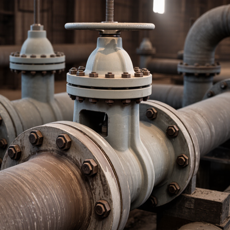
A ceramic knife gate valve uses a thin blade, or gate, that moves across the flow path. In many designs, ceramic liners or seat faces protect the areas exposed to abrasive slurry. When the valve opens, the gate lifts clear of the passage, leaving a relatively unobstructed opening. When it closes, its sharpened lower edge can cut through settled solids. That detail matters.

The gate is moved by a handwheel or an actuator, depending on valve size and operating needs. The ceramic surfaces resist abrasion, but they are hard and can be brittle. A sudden impact or rapid temperature change may damage them. In service, check that the piping is aligned and the valve is not forced shut against a trapped lump. Small details matter here.

These valves are generally intended for isolation, not precise flow control. Partly open operation can expose the gate and seats to concentrated wear, even when the ceramic appears sound. I would also verify the slurry’s particle size, temperature, and pressure against the valve’s specified limits; “abrasion resistant” does not mean suitable for every mixture. Real installations are rarely perfect, so inspection intervals may need adjustment after observing actual wear.

Assessing Process Media, Pressure, Temperature, and Flow Conditions

How to Choose the Right Ceramic Knife Gate Valve?
Assessing Process Media, Pressure, Temperature, and Flow Conditions

Start with the media, not the valve size. Identify its chemistry, solids, particle shape, and concentration. Abrasive slurry with sharp mineral grains can wear a seat differently from fine, dilute particles. Check whether the ceramic grade and seals tolerate the actual fluid, including cleaning chemicals and temperature changes. A compatibility chart is only a starting point; real mixtures can behave differently.

Pressure needs careful reading. Record both operating pressure and the maximum differential pressure across the closed gate, including start-up and blockage scenarios. ASME B16.34 organizes pressure-temperature ratings by material group and class, but those ratings should not be transferred blindly to a ceramic-lined assembly. Ask for the complete valve’s limits. Important distinction.

Temperature affects more than the ceramic. Packing, elastomers, body materials, and thermal expansion all matter. Note normal, peak, and cycling temperatures. A rapid temperature swing may be more concerning than a steady hot process. ISO 5208 defines leakage Rate A as no visually detectable leakage during its test; that result is not a guarantee of zero leakage in every installation.

Finally, compare flow velocity and solids settling risk at minimum and maximum flow. Oversizing may encourage deposits; undersizing can raise wear and pressure loss. Check the manufacturer’s flow data against your process figures, then review shutdown and flushing conditions. I would challenge any selection based on nominal pipe size alone.

How to Choose the Right Ceramic Knife Gate Valve

Assess process media, pressure, temperature, and flow conditions before selecting a valve. The chart shows water’s saturation pressure at selected temperatures; it is process-reference data, not a valve pressure rating.

For slurry or solids service, also evaluate particle size, concentration, abrasiveness, and required flow. Confirm the valve’s material compatibility and pressure-temperature limits for your specific operating conditions.

Selecting Ceramic Materials and Valve Components for Wear Resistance

How to Choose the Right Ceramic Knife Gate Valve?

Selecting ceramic materials and valve components for wear resistance starts with the process conditions. Identify the slurry’s solids, particle size, flow speed, temperature, and chemical makeup. Alumina ceramic can suit many abrasive services, while tougher ceramic grades may better tolerate impact. Neither choice works everywhere. Request test data for the actual operating conditions, not just a hardness figure.

Match the ceramic parts to the whole valve. The gate and seat need compatible contact surfaces, while the body must support them without uneven loading. Check seal material, stem alignment, and actuator force; poor alignment can chip a ceramic edge. In practice, a valve may wear unevenly when particles collect near the seat. That detail is easy to miss on a specification sheet. Ceramic resists abrasion, but it can fracture under sudden impact, so installation and handling matter.

Tips: Ask about the ceramic grade, lining thickness, and wear-test method. Confirm the expected solids concentration and flushing procedure. Inspect the seat and gate during planned maintenance. A small amount of process data can prevent a costly mismatch.

Choosing Valve Size, Connection Type, and Actuation Method

Choosing the right ceramic knife gate valve starts with the duty, not just the pipe diameter. Match valve size to flow rate, slurry concentration, and acceptable pressure drop. A valve that is too large may allow solids to settle; one that is too small can restrict flow and increase wear. Check the operating pressure and temperature against the valve’s specifications. Ceramic surfaces resist abrasion, but impact from large particles can still cause damage. Small details matter.

Connection type should suit the existing pipeline and the maintenance plan. Flanged ends provide a familiar, secure option, while wafer-style designs may save space between pipe flanges. Confirm face-to-face dimensions, flange standards, and room for bolt removal before ordering. For actuation, handwheels can suit accessible lines with infrequent operation. Pneumatic or electric actuators may be preferable for frequent cycling or remote control. Verify the required opening force, available utilities, control signals, and whether the valve must move to a safe position during power loss. That last detail is easy to overlook.

Tips: Measure the pipe and installation clearance on site. Share actual slurry conditions with the supplier, including particle size and solids content. If conditions vary, leave time to review the selection with an applications engineer.

How to Choose the Right Ceramic Knife Gate Valve? - Choosing Valve Size, Connection Type, and Actuation Method

Selection Dimension Typical Options or Inputs How to Choose Key Checks Before Ordering
Nominal valve size Common nominal sizes range from small-bore valves to large pipeline valves; availability depends on the valve design. Start with the connected pipe’s nominal size and required flow capacity. Do not select a smaller valve solely to increase velocity without checking pressure loss, wear, and process requirements. Confirm pipe size, required flow rate, slurry concentration, particle size, and the manufacturer’s flow and pressure data.
Operating conditions Process pressure, temperature, flow direction, solids content, and frequency of operation. Choose a valve design and ceramic trim suited to the actual abrasive or corrosive service. Ceramic components can resist wear, but allowable limits vary by design and material. Check the rated pressure and temperature, pressure differential, media compatibility, and whether the valve is intended for throttling or isolation.
Connection type Wafer, lug, or flanged connections are common configurations, subject to product design. Use wafer connections where the pipe layout and flange arrangement support installation between flanges. Consider lug or flanged designs where the piping arrangement or removal requirements call for them. Match flange standard, pressure class, facing, bolt pattern, and face-to-face dimensions to the piping specification.
Installation orientation and space Horizontal or vertical pipe runs; available clearance around the valve and actuator. Follow the valve maker’s installation guidance, especially for abrasive slurry and solids that may settle. Allow clearance for the gate, stem, actuator, and maintenance access. Verify flow direction where specified, mounting position, adjacent-pipe support, overall dimensions, and actuator removal clearance.
Manual actuation Handwheel or other manual operator, depending on valve size and design. Consider manual operation for infrequent use, accessible locations, and applications where the required operating effort is practical. Confirm operating torque or thrust, operator arrangement, accessibility, and any need for a locking device.
Pneumatic actuation Single-acting or double-acting actuator, depending on the required operating behavior and available air supply. Consider pneumatic actuation for remote or frequent operation where a suitable instrument-air supply is available. Select the fail position only after reviewing process and safety requirements. Provide actuator supply pressure, required stroke time, control signal or solenoid requirements, and the valve’s operating thrust across the full pressure differential.
Electric actuation Electric actuator with suitable power supply, controls, and feedback options. Consider electric actuation when plant power and control-system integration are preferred or instrument air is unavailable. Confirm voltage, frequency, enclosure and environmental requirements, duty cycle, control mode, feedback, and required operating thrust.
Final actuator sizing Valve size alone does not determine actuator size. Size the actuator using the valve’s required thrust or torque under the most demanding specified operating conditions, with appropriate design allowance. Ask for the valve’s thrust or torque data, maximum differential pressure, seat and packing details, and actuator sizing calculations.

Note: Confirm dimensional standards, pressure and temperature limits, materials, and actuator sizing with the valve supplier for the specific process conditions and piping specification.

Checking Installation, Maintenance, and Supplier Requirements

How to Choose the Right Ceramic Knife Gate Valve?

Checking Installation, Maintenance, and Supplier Requirements

Installation details can decide whether a ceramic knife gate valve lasts or chips early. Check the pipe alignment, flange faces, and available clearance before lifting the valve into place. Ceramic components resist abrasion, but they can be vulnerable to impact and uneven loading. Keep the gate clear of hardened slurry, and follow the manufacturer’s specified bolt-tightening sequence. Small practical details matter.

Maintenance planning should reflect the actual slurry, not just the valve’s nameplate. Record operating pressure, temperature, solids concentration, and cleaning frequency. During inspections, look for seat wear, deposits, leakage, and damage around ceramic edges. Never use a metal tool to force a stuck gate. The U.S. Department of Energy’s Improving Pumping System Performance sourcebook reports that pumping systems can consume 25–50% of energy in some industrial facilities. That figure is not a valve-savings estimate, but it highlights why avoiding unnecessary pressure loss and poor installation deserves attention.

Ask suppliers for written limits on pressure, temperature, particle size, and compatible process media. Request material traceability, inspection records, spare-part availability, and clear installation instructions. ISO 5208 provides pressure-testing requirements for industrial valves; confirm which tests apply to the selected design. I would still verify the details against your process conditions. A tidy datasheet can miss a messy site reality.

Shopping Cart
Scroll to Top

Search for...

The Duravant family of operating companies serve the food processing, packaging and material handling segments.