

How to Choose the Right Electro Hydraulic Valve?

Choosing the right Electro-Hydraulic Valve is not a simple catalog exercise. The decision affects motion accuracy, energy use, safety, and maintenance time. A valve controlling a stamping cylinder may face sudden pressure spikes, while one driving a robotic gripper may require smoother, faster response.

Industry data shows why this choice matters. The International Federation of Robotics reported 4.28 million industrial robots operating worldwide in 2023 in its World Robotics 2024 report. More automated equipment means tighter demands on hydraulic control. Meanwhile, ISO 4413 emphasizes risk reduction, pressure control, cleanliness, and safe system design in hydraulic applications. These references provide a useful foundation, but they do not select the valve for you.

The right model depends on several physical details. Check flow rate, maximum pressure, response time, spool design, control signal, fluid type, and mounting interface. Do not ignore contamination. A small particle can damage a precision valve and create unstable cylinder movement. Confirm the machine’s duty cycle, temperature range, and emergency-stop requirements. Then compare proportional, servo, and on-off technologies against actual performance needs.

There is no universal winner.

A low-cost valve may appear efficient during purchase. It may become expensive through leakage, downtime, or repeated calibration. Manufacturers’ datasheets are valuable, yet field experience often reveals the missing details: noise at peak flow, heat near the coil, or delayed response after long operation. This guide connects published industry evidence with practical selection steps, helping engineers make a defensible choice rather than relying on habit.
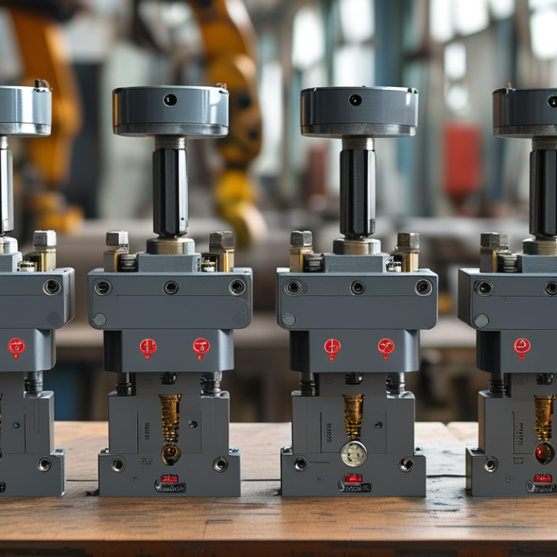
How to Choose the Right Electro Hydraulic Valve?

Classify Valve Types: 2/2, 3/2, 4/3, Proportional, and Servo Designs

How to Choose the Right Electro Hydraulic Valve?

Valve selection begins with movement requirements, not catalogue photographs.

A 2/2 valve has two ports and two positions, making it suitable for simple flow isolation.

A 3/2 valve adds a third port and commonly controls single-acting cylinders. It can vent pressure quickly.

A 4/3 valve serves double-acting actuators and offers three spool positions. Its center condition must match the pump, load, and safety response.

Proportional valves regulate flow or pressure continuously through an electrical command. They suit speed control, clamping, and changing loads.

Servo valves provide tighter response and usually require feedback, clean oil, and careful commissioning.

According to MarketsandMarkets’ Industrial Valves Market report, the global market may grow from about USD 75.3 billion in 2023 to USD 97.3 billion by 2028. This growth reflects broader automation, not automatic justification for servo control.

Start with the circuit.

Field testing often reveals a weak assumption: more precision is not always better. A 4/3 valve may outperform a proportional valve when stable center behavior matters more than smooth adjustment.

Grand View Research estimates the hydraulic valves market will expand at a mid-single-digit compound annual growth rate through 2030. That trend encourages smarter controls, but contamination can quickly damage fine-tolerance components.

Check response time
leakage
pressure drop
oil cleanliness
emergency behavior

Specify electrical feedback only when measured accuracy improves the actual machine process.

Match Pressure and Flow Ratings: Compare 210–350 bar and L/min Requirements

Choosing the right electro hydraulic valve starts with pressure and flow, not connector type. A 210 bar circuit should not use a valve rated only for normal working pressure. Pressure spikes, shock loads, and cold-start conditions require safety margin. ISO 4413 recommends rating components for the maximum system pressure, including foreseeable surges. Check the pump outlet, relief-valve setting, and actuator load together.

Flow Capacity
Flow capacity is equally important. A valve marked 40 L/min may perform poorly when the system needs 38 L/min continuously. Pressure loss can increase heat, noise, and response delay. For example, a 250 bar excavator circuit may need 32 L/min during steady movement, but 45 L/min during rapid extension. Select the valve from the real peak flow, then verify the manufacturer’s pressure-drop curve. Do not rely on the port size alone.

Recent 2024 market reports from MarketsandMarkets and Research and Markets place the global hydraulic equipment market above 40 billion US dollars. Their forecasts differ because market definitions vary, which is worth remembering. Industry growth does not make every valve suitable. NFPA hydraulic guidance also emphasizes matching rated pressure, flow, fluid condition, and control duty. In field testing, I would record pressure before and after the valve at several flow rates. A small mistake here can become a hot manifold and unstable motion. Sometimes, the “correct” valve still needs a larger return line.

Evaluate Response and Accuracy: Servo Valves Below 10 ms for Precision Control

Choosing the Right Electro Hydraulic Valve: Evaluate Response and Accuracy

For precision motion, a servo valve with a response time below 10 ms can reduce lag noticeably. This matters in testing machines, injection equipment, and flight-control simulators. However, the number needs context. Check whether the manufacturer measured step response, frequency response, or signal delay. These tests can produce very different results.

In field commissioning, I watch the actuator move against a marked scale. A fast valve is not automatically accurate. Position feedback, spool overlap, hysteresis, and oil cleanliness also affect performance. A valve may respond within 8 ms, yet still overshoot when pressure changes quickly. That weakness often appears during acceleration, not during a bench test. Small details matter.

Ask for repeatability data at your working pressure and flow rate. Confirm the response curve, allowable contamination level, and control-signal requirements. A stable amplifier and a properly tuned controller are equally important. Keep the hydraulic lines short. Remove trapped air. These steps sound basic. They are often missed. I have also seen excellent specifications fail in practice because the test oil was warmer than the production oil. Therefore, compare results under realistic temperature, load, and backpressure conditions. Below 10 ms is a useful target, not a complete selection rule.

How to Choose the Right Electro Hydraulic Valve? - Evaluate Response and Accuracy: Servo Valves Below 10 ms for Precision Control

Valve Type Typical Step Response
(10–90%)
Flow Command Accuracy
(Typical)
Hysteresis
(Typical)
Repeatability
(Typical)
Rated Pressure Range Control Signal Recommended Applications Selection Consideration
High-Response Servo Valve Typically below 10 ms Approximately ±0.5–1% of rated flow Usually below 3% Typically below 0.5% Commonly 210–350 bar ±10 V, ±20 mA, or digital command Test systems, flight-motion simulation, injection molding, high-dynamic positioning Requires clean hydraulic fluid, stable electronics, and careful tuning
High-Performance Proportional Valve Approximately 10–30 ms Approximately ±1–2% of rated flow Typically 3–6% Typically below 1% Commonly 160–350 bar 0–10 V, ±10 V, or 4–20 mA Machine tools, robotics, material handling, closed-loop motion control Good balance of dynamic performance, cost, and contamination tolerance
Standard Proportional Valve Approximately 30–100 ms Approximately ±2–5% of rated flow Typically 5–10% Typically 1–3% Commonly 100–315 bar 0–10 V, 4–20 mA, or PWM General industrial automation, presses, conveyors, lifting equipment Suitable when moderate speed and accuracy are acceptable
Proportional Pressure-Control Valve Approximately 20–80 ms Approximately ±1–3% of pressure range Typically 3–8% Typically 1–2% Commonly 100–350 bar 0–10 V, 4–20 mA, or PWM Clamping, tension control, force regulation, hydraulic power management Select according to pressure stability, flow demand, and relief requirements
On/Off Solenoid Valve Approximately 20–100 ms switching time Not intended for continuous flow modulation Not normally specified for proportional control Defined by switching consistency Commonly 100–350 bar Discrete DC or AC voltage Basic directional control, safety isolation, sequencing, and simple actuators Use when two-position control is sufficient and precision is not critical
Technical note: The values shown are representative engineering ranges rather than guaranteed specifications. Actual response time and accuracy depend on valve size, pressure drop, hydraulic fluid cleanliness, spool overlap, amplifier settings, actuator load, piping, temperature, and feedback-loop tuning. Response time should be compared using the same test method, command amplitude, rated flow, and operating pressure.

Verify Fluid Conditions: ISO 4406 Cleanliness and 40–80°C Temperature Limits

Choosing the right electro hydraulic valve begins with fluid condition, not port size alone. In field inspections, contamination often causes sluggish movement, leakage, and unexpected coil cycling. Ask for the fluid’s ISO 4406 cleanliness code before selecting the valve. This code reports particle counts at three size ranges. A lower code means cleaner fluid. Do not treat it as a decorative number. It affects internal clearances and service life.

Compare the measured code with the valve’s cleanliness requirement and the circuit’s weakest component. Take a sample from a live, well-flushed line, using a clean bottle and proper sampling method. A dirty sampling point can create a false warning. It can also hide a real problem. Record the result, filter condition, reservoir history, and operating hours. I would repeat the test after commissioning. Installation debris is easy to underestimate.

Temperature needs equal attention. Keep the hydraulic fluid within the specified 40–80°C range only when the valve and fluid documentation allow it. At higher temperatures, viscosity can fall, seals may age faster, and leakage can increase. At lower temperatures, pressure losses and slow response may appear. Measure fluid temperature near the valve, not only at the reservoir. A single reading is weak evidence. Check cold starts, peak loads, and long duty cycles. If results conflict, pause the selection and question the assumptions.

Check Electrical and Safety Features: 24 VDC, IP65, and Fail-Safe Functions

When selecting an electro hydraulic valve, examine its electrical and safety features before comparing flow rates. A 24 VDC coil often suits mobile equipment and industrial control panels. It can reduce shock risk and simplify PLC integration. However, verify voltage tolerance, current draw, polarity, and connector wiring. A small mismatch may cause overheating or unreliable switching.

IP65 protection means the enclosure resists dust and water jets. It does not mean the valve can stay underwater. Check the mounting position, cable gland, and connector seal. In field inspections, moisture often enters through damaged cables rather than the valve body. I once overlooked this detail during a maintenance review. The valve passed a bench test but failed after outdoor installation. That mistake changed my inspection checklist.

Fail-safe operation deserves careful attention. Ask what happens when power, signal, or hydraulic pressure disappears. A spring-return design may move the actuator to a safer position, but that position depends on the machine’s hazards. Confirm whether the valve de-energizes to extend, retract, hold, or release pressure.

Test the actual failure condition, not only normal operation. Review the wiring diagram, safety data, and maintenance instructions with qualified personnel. A manual override can help during servicing, yet it may also create unexpected movement. Clear labels and physical guarding remain necessary. Safety depends on the complete system, not one valve feature.

Shopping Cart
Scroll to Top

Search for...

The Duravant family of operating companies serve the food processing, packaging and material handling segments.