What Is an SMA Antenna and What Is It Used For?
An Sma Antenna is an antenna fitted with a threaded SMA coaxial connector. SMA describes the connection, not one specific antenna design. The antenna itself may be a short whip, a compact PCB element, or a directional unit. Its connector lets it attach to compatible radios, cables, and test equipment. Small connector. Important distinction.
A useful starting point is antenna expert Constantine A. Balanis’s description: “An antenna is a transitional structure between free-space and a guiding device.” His textbook, Antenna Theory: Analysis and Design, explains the broader role antennas play in radio systems. An SMA connector provides the physical and electrical interface; it does not, by itself, guarantee range, gain, or frequency coverage. Check the antenna’s datasheet, including impedance, operating band, and connector gender, before choosing one.
The wider wireless market helps explain why compact RF components matter, though it does not measure SMA antenna sales directly. Ericsson’s 2024 Mobility Report forecasts about 6.3 billion 5G subscriptions worldwide by 2030. That growth supports demand for connected devices and radio hardware, but an SMA antenna is only one possible component in those systems. You may find one on a lab instrument, a wireless development board, or an external router antenna. The details matter. A connector that fits can still be electrically unsuitable. And a datasheet can leave practical questions unanswered, such as performance near metal surfaces. Understanding the connector and antenna together is the real starting point.
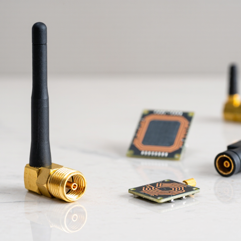
What an SMA Antenna Is: A 50-Ohm RF Antenna with a Threaded Connector
An SMA antenna is an RF antenna fitted with an SMA connector, a small threaded interface commonly designed for 50-ohm systems. The connector lets the antenna attach securely to compatible radios, modules, cables, or test equipment. Its metal threads resist loosening when a device is moved, while the coaxial connection carries the radio-frequency signal. It is a practical fit for compact equipment. The thread is not the antenna’s radiating element; it is the connection point.
You may find SMA antennas on wireless development boards, GPS receivers, handheld radios, and measurement setups. A short whip can suit a nearby link, while a directional antenna may help focus reception in a particular direction. Connector gender and frequency range matter. So does impedance. A mismatch between a 50-ohm antenna and the connected system can reduce signal transfer, though cable loss, placement, and nearby metal also affect performance. Check the device documentation before connecting anything. That detail matters. I still find it easy to focus on the connector and overlook the antenna’s operating band. An SMA plug alone does not guarantee compatibility, and adapters can add loss or mechanical strain. Keep the antenna upright when its design calls for it, and avoid forcing the threads. A snug connection is enough.
What is an SMA antenna? It is an RF antenna connected through a threaded SMA coaxial interface, commonly designed for a 50-ohm system. The chart shows the corresponding free-space wavelength at selected frequencies. Wavelength helps explain antenna sizing, but the actual antenna’s frequency range and dimensions depend on its design.
How SMA Connectors Work: 50 Ω Impedance and Secure Threaded Coupling
An SMA antenna connects through a compact coaxial interface designed for a nominal 50 Ω system. That value matters: when the antenna, cable, and radio share the same impedance, less signal reflects back toward the source. The IEC 61169-15:2015 interface specification covers SMA connectors, while MIL-STD-348B documents RF connector interface dimensions. For common SMA assemblies, the operating range often reaches 18 GHz, but the actual limit depends on the connector, cable, and assembly quality. Check the component specification.
The threaded coupling helps keep the connection seated when equipment moves or cables bend. Its small metal nut can feel secure, but overtightening may damage the interface. Many standard SMA connections use about 0.56 N·m (5 in·lbf) of torque; use the value specified for the specific assembly. Small detail. It matters. A loose connection can create inconsistent readings, especially during repeated measurements. Keep the mating surfaces clean, align the threads by hand, and avoid twisting the cable while tightening. In practice, connector wear and hurried handling can undermine an otherwise sound 50 Ω setup. That is easy to miss.
SMA Frequency Limits: Standard Interfaces Commonly Operate up to 18 GHz
SMA means SubMiniature version A, a threaded coaxial interface used on antennas, test leads, and compact radio-frequency equipment. Standard SMA assemblies are commonly specified for operation up to 18 GHz. This is a practical rating, not a universal guarantee. IEC 60169-15:2011 defines the SMA connector interface, while individual component specifications determine electrical performance. Check the specified frequency range for both mating connectors, the cable, and any adapter; the lowest-rated part sets the usable limit.
The details matter. At 18 GHz, a loose connection, worn threads, or a poorly designed circuit-board launch can increase reflections and signal loss. Even a short adapter can affect measurements. A low voltage standing wave ratio (VSWR) specification indicates better impedance matching, but its value should be checked across the intended frequency band, not at one convenient test point. For example, a connector rated to 18 GHz may not deliver the same performance when installed on a cable assembly with a lower rating. The number sounds tidy, but system performance depends on the whole path. For a design near the upper limit, verify insertion loss and return loss using the component’s test data, then validate the assembled setup with calibrated equipment.
What Is an SMA Antenna and What Is It Used For? — SMA Frequency Limits: Standard Interfaces Commonly Operate up to 18 GHz
| Dimension | Typical Information | Practical Notes |
| What “SMA antenna” means | An antenna fitted with an SMA coaxial connector, or an antenna designed to connect to equipment with an SMA port. | SMA describes the connector interface, not the antenna’s radiation pattern or operating frequency. |
| Connector type | Threaded coaxial interface, commonly used with 50-ohm RF systems. | Standard SMA uses a 1/4-36 thread. Check connector gender and pin/socket configuration before mating. |
| Common frequency limit | Standard SMA interfaces commonly operate from DC to 18 GHz. | The usable limit depends on the connector, cable, assembly, and mating condition. Some precision SMA components are specified for higher frequencies. |
| Impedance | 50 Ω is the usual impedance for SMA RF connectors and antennas. | Match the antenna, cable, and radio impedance to reduce reflections and signal loss. |
| Common applications | Wireless networking, telemetry, GNSS receivers, cellular equipment, radio modules, and RF test setups. | The antenna must be designed for the specific radio band and installation environment. |
| Example operating bands | 2.4 GHz ISM band (2.400–2.4835 GHz); GNSS GPS L1 (1575.42 MHz); selected 5 GHz wireless LAN bands. | Band availability and channel ranges can vary by radio standard and region. Confirm the antenna’s stated frequency range. |
| Cable and installation effects | Cable length, cable type, adapters, and connector quality affect insertion loss and system performance. | Use the shortest practical cable and minimize adapters, especially at higher frequencies. |
| Connection care | Keep mating surfaces clean, align the threads, and tighten using the connector manufacturer’s specified method. | Avoid cross-threading and excessive torque, which can damage the connector and affect RF performance. |
Where SMA Antennas Are Used: Wi-Fi, GNSS, IoT, and RF Test Equipment
An SMA antenna connects through a compact, threaded coaxial fitting, making it practical for radios, gateways, and measurement instruments. The screw-on connection is easy to inspect on a crowded bench. It is not a performance guarantee: frequency range, antenna tuning, cable loss, and placement still matter.
For Wi-Fi, SMA antennas are common on access points and embedded devices that need an external antenna. A Wi-Fi Alliance report estimated Wi-Fi’s global economic value at 4.9 trillion US dollars in 2025.
In GNSS receivers, an SMA-fed antenna can sit near a window or on a vehicle roof, away from shielding metal. The European Union Agency for the Space Programme’s 2024 market report projected GNSS downstream revenues could rise from about €260 billion in 2023 to €580 billion by 2033.
IoT gateways also use SMA connections for cellular, sub-GHz, or other radio links. IoT Analytics estimated 18.8 billion connected IoT devices worldwide by the end of 2024. A small connector supports a very large ecosystem.
RF test equipment uses SMA ports to attach antennas, cables, and loads during repeatable measurements. Engineers can compare signal strength or check coverage at a fixed position. Tiny setup changes can skew results. SMA parts also vary in quality, and frequent mating can wear the interface; that detail is easy to overlook.
How to Choose One: Match Frequency, Gain, Polarization, and VSWR (Often ≤2:1)
An SMA antenna uses a threaded SubMiniature version A connector, but the connector alone says little about antenna performance. Match the antenna’s specified operating band to your device’s actual frequencies, including channel edges. A mismatch can reduce radiation efficiency even when the connector fits perfectly. Check measured performance across the full band, not just at its center. IEEE Std 145-2013 standardizes antenna terms such as gain and polarization, helping make datasheet comparisons clearer. Still, the mounting setup matters.
Gain describes how energy is directed, not how much power the antenna creates. Higher gain can improve coverage in some directions while narrowing it in others. ITU-R Recommendation P.525-4 (2021) gives the free-space path-loss method; at 2.4 GHz over 10 metres, the loss is about 60 dB. Treat that as a baseline, since walls and nearby metal change real results. Match polarization too: a vertical antenna may perform poorly against a horizontally oriented one. Check the mounting. For VSWR, 2:1 corresponds to about 11% reflected power, or 9.5 dB return loss. It is a common target, not a guarantee of good range. A short antenna mounted on a metal enclosure may behave differently from its datasheet setup, so verify it in the final assembly.